
ONE LINE OF BASIC.
Every card described on this page is still in preparation. They are being redesigned so that a card can be plugged in and pulled out without putting the machine at risk — which is the sort of thing you want settled before you sell somebody a laboratory rather than after.
When each one is finished and in the shop, we will say so here. It is worth looking in from time to time. The point of the whole range is to open the Spectrum up — to give it hands and senses, and to give whoever is sitting in front of it something real to learn on.
Before we built computers, we built things to plug into them. MUMIO is a family of peripherals for the ZX Spectrum, laid out along the same lines as Arduino shields — except you drive them from BASIC.
Everything mounts on an addressable I/O card that sits in the edge connector at the back. Each card takes an address from 0 to 255 on an eight-position switch, so you can chain a great many of them and talk to each in turn.
The card keeps the Spectrum’s bus safely at arm’s length. You never need to know how the edge connector is wired, or what the Z80 is doing underneath — which is rather the point.
A TOOLCHAIN
A modern microcontroller board needs an environment installed, drivers, a compiler and a cable. A Spectrum needs a power lead.
Type OUT 31,255 and press ENTER. Something happens immediately. There is no build step between the idea and the result, and for somebody learning, that gap is where most of them give up.
Learn the ideas here, move to C on a microcontroller when they have stuck. It is a gentler road into automation than most people get offered.
Watch this page.
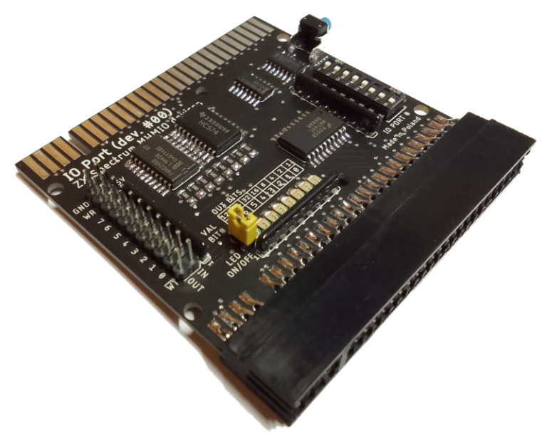
Eight-bit input and output card with a pass-through connector and a RESET button. Eight outputs, latched and shown on LEDs; eight inputs, not latched. Address set on a DIP switch, 0–255. This is the foundation — everything else sits on top of it.
FULL SPECIFICATION →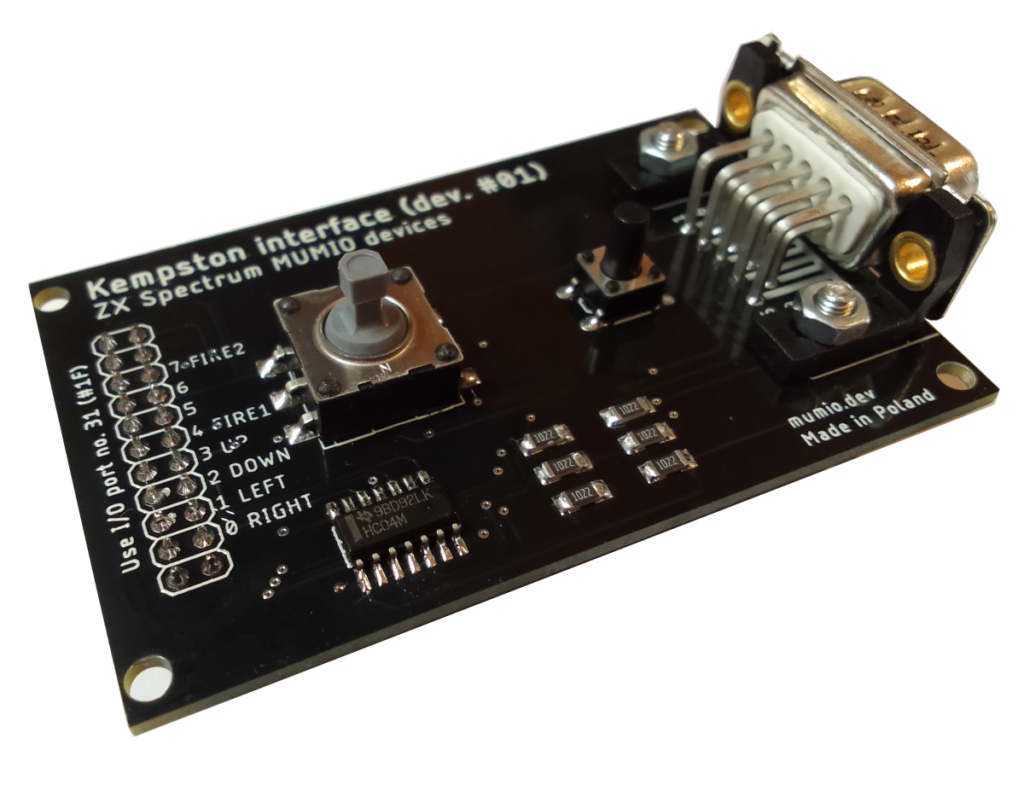
Joystick interface to the Kempston standard, so any controller built to that standard will work. There is a small two-button joystick on the board itself, for when you cannot find the real one.
FULL SPECIFICATION →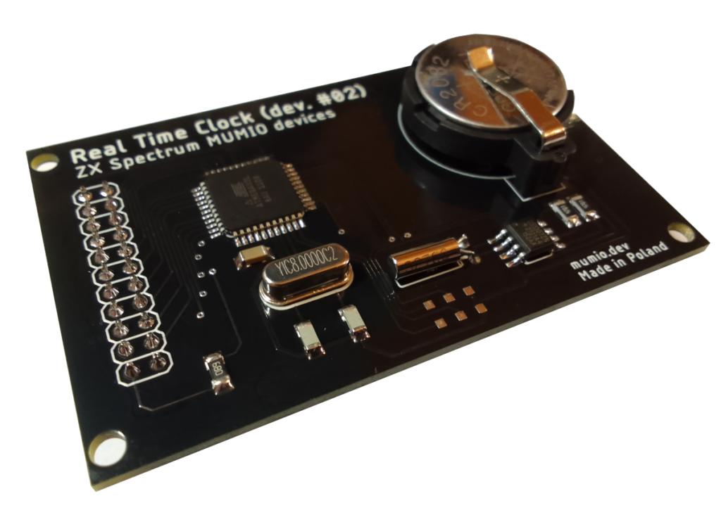
A DS1307 keeping year, month, day, hour, minute and second, ticked by a 32 768 Hz crystal. An ATmega32 sits between it and the MUMIO bus to keep the protocol simple. Reads and sets from BASIC, and works with esxDOS so your files finally get sensible timestamps.
FULL SPECIFICATION →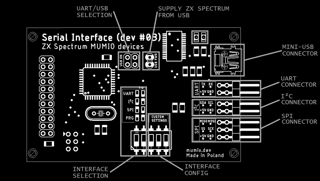
UART (RS-232), SPI, I²C and USB on one board — the four interfaces automation actually runs on. This is what lets a 1982 machine talk to a modern sensor, or to a PC, without anybody pretending the intervening forty years did not happen.
FULL SPECIFICATION →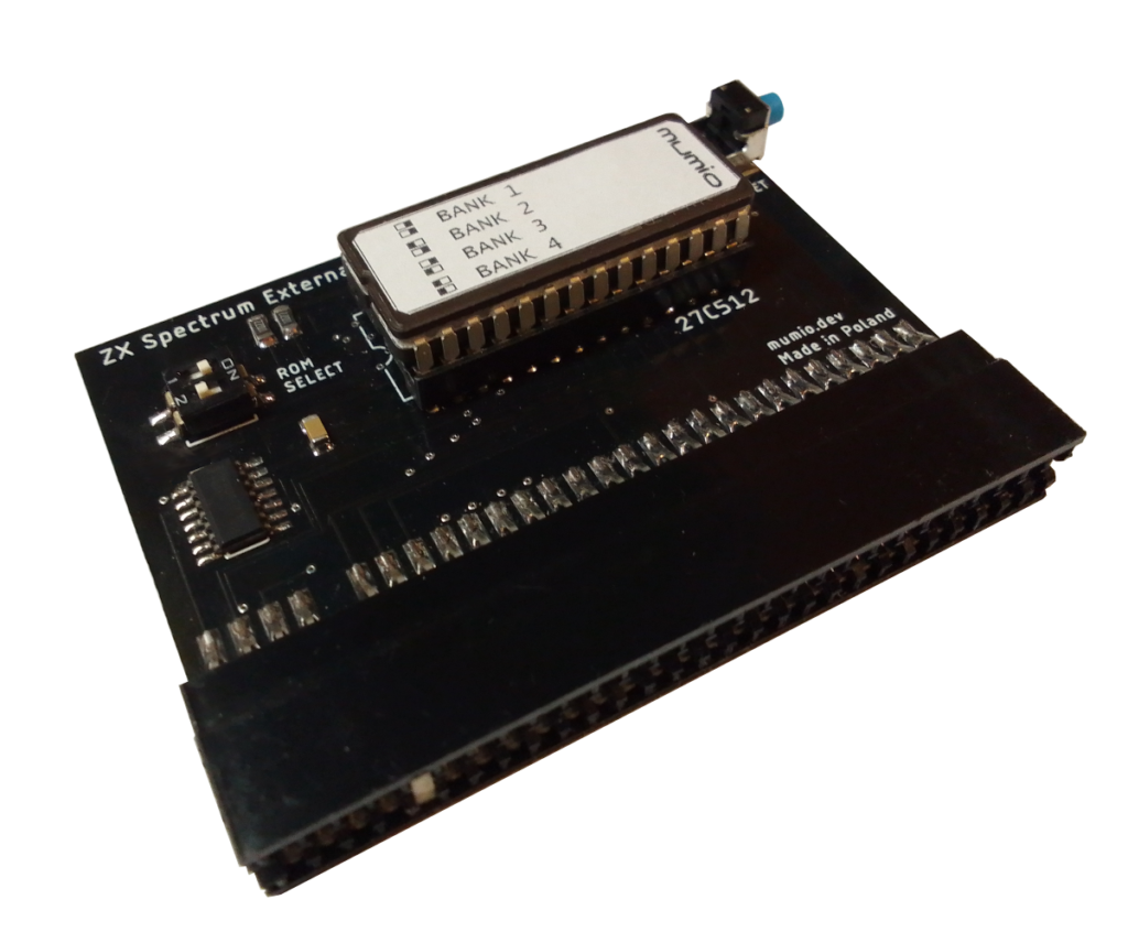
A 27C512 EPROM holding 64 KB — four switchable 16 KB ROMs — in place of the one Sinclair fitted. For servicing: memory, ULA, keyboard, EAR/MIC, picture and sound all get tested from a ROM that boots the instant you switch on.
There is a footnote worth knowing here. The original 1982 ROM shipped with bugs the manufacturer knew about and never fixed — the whole BASIC interpreter, the character set and a handful of useful routines squeezed into sixteen kilobytes, and that was that. Several corrected and extended versions exist today, and this is how you run them.
FULL SPECIFICATION →CAN’T BUY
THEM TODAY.
Drive a servo, a motor, a relay
Put text on an external display
Set and read the clock, timestamp files
Talk to Arduino modules over I²C or SPI
Test a sick Spectrum from a diagnostic ROM
If you teach, run a club, or simply want a particular module to exist, we would genuinely like to hear it before the redesign is finished. Several of the boards above began as somebody’s request.
GET IN TOUCH →